
Product Description
SC Transmission FCL Flexible Shaft Couplings for Reducer and Motor
Product Description
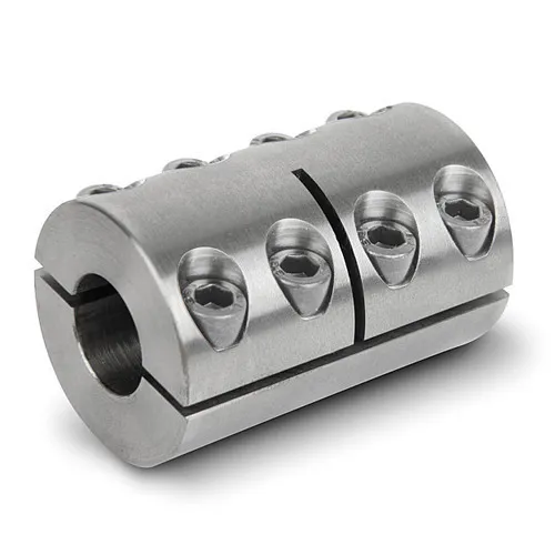
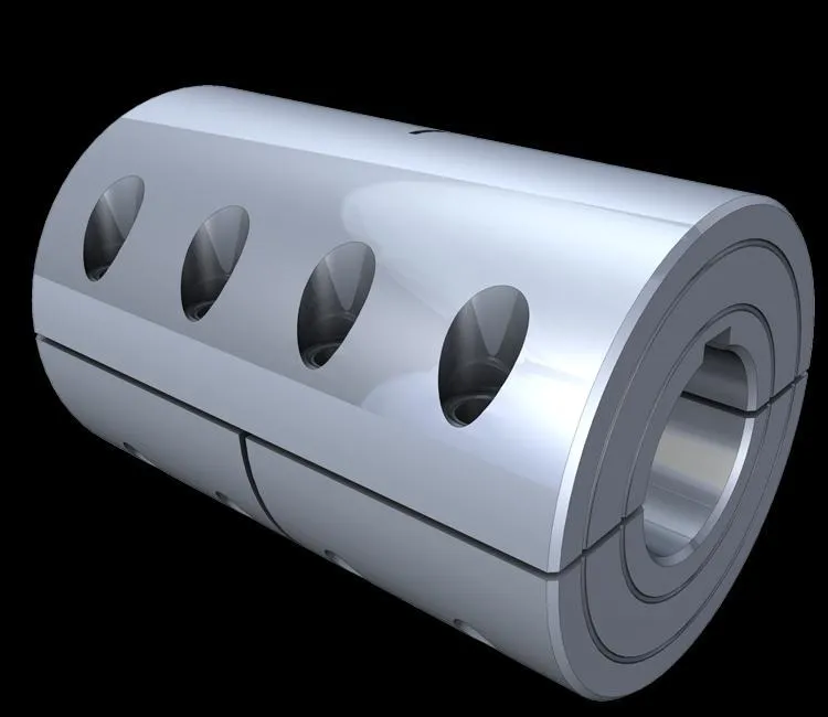
FCL Coupling/Shaft Coupling /Pin & Bush Coupling /FCL Flexible Coupling/NBK FCL Coupling is widely used for its compacts designing, easy installation, convenient maintenance, small and light weight.
As long as the relative displacement between shafts is kept within the specified tolerance, couplings will operate the best function and have a longer working life.
Thus it is greatly demanded in medium and minor power transmission systems driven by motors, such as speed reducers, hoists, compressors, conveyors, spinning and weaving machines and ball mills.
Product Parameters
| SIZE | D | D1 | d1 | L | C | n-M | kg | |||
| r/min | ||||||||||
| N.m | ||||||||||
| FCL90 | 4 | 4000 | 90 | 35.5 | 11 | 28 | 3 | 4-M8 | 1.7 | |
| FCL100 | 10 | 4000 | 100 | 40 | 11 | 35.5 | 3 | 4-M10 | 2.3 | |
| FCL112 | 16 | 4000 | 112 | 45 | 13 | 40 | 3 | 4-M10 | 2.8 | |
| FCL125 | 25 | 4000 | 125 | 65 | 50 | 13 | 45 | 3 | 4-M12 | 4 |
| FCL140 | 50 | 4000 | 140 | 71 | 63 | 13 | 50 | 3 | 6-M12 | 5.4 |
| FCL160 | 110 | 4000 | 160 | 80 | 15 | 56 | 3 | 8-M12 | 8 | |
| FCL180 | 157 | 3500 | 180 | 90 | 15 | 63 | 3 | 8-M12 | 10.5 | |
| FCL200 | 245 | 3200 | 200 | 100 | 21 | 71 | 4 | 8-M20 | 16.2 | |
| FCL224 | 392 | 2850 | 224 | 112 | 21 | 80 | 4 | 8-M20 | 21.3 | |
| FCL250 | 618 | 2550 | 250 | 125 | 25 | 90 | 4 | 8-M24 | 31.6 | |
| FCL280 | 980 | 2300 | 280 | 140 | 34 | 100 | 4 | 8-M24 | 44 | |
| FCL315 | 1568 | 2050 | 315 | 160 | 41 | 112 | 4 | 10-M24 | 57.7 | |
| FCL355 | 2450 | 1800 | 355 | 180 | 60 | 125 | 5 | 8-M30 | 89.5 | |
| FCL400 | 3920 | 1600 | 400 | 200 | 60 | 125 | 5 | 10-M30 | 113 | |
| FCL450 | 6174 | 1400 | 450 | 224 | 65 | 140 | 5 | 12-M30 | 145 | |
| FCL560 | 9800 | 1150 | 560 | 250 | 85 | 160 | 5 | 14-M30 | 229 | |
| FCL630 | 15680 | 1000 | 630 | 280 | 95 | 180 | 5 | 18-M30 | 296 | |
Company Profile
FAQ
Shipping
/* January 22, 2571 19:08:37 */!function(){function s(e,r){var a,o={};try{e&&e.split(“,”).forEach(function(e,t){e&&(a=e.match(/(.*?):(.*)$/))&&1
How does misalignment affect the performance and reliability of muff couplings?
Misalignment in muff couplings can have significant negative effects on their performance and overall reliability. Misalignment occurs when the connected shafts are not perfectly aligned, causing angular, parallel, or axial deviations. Here’s how misalignment impacts muff coupling performance:
- Reduced Torque Transmission: Misalignment increases stress concentrations in the muff coupling, reducing its ability to transmit torque efficiently. This can lead to premature wear, deformation, or failure of the coupling.
- Increased Wear and Fatigue: Misalignment causes uneven loading on the coupling’s components, leading to accelerated wear and fatigue. This can result in shortened muff coupling lifespan and frequent maintenance requirements.
- Vibration and Noise: Misalignment generates vibrations and noise due to uneven forces acting on the muff coupling. These vibrations can affect nearby components and machinery, leading to increased wear and decreased overall system efficiency.
- Shaft and Bearing Damage: Misalignment places additional loads on connected shafts and bearings. This can lead to premature wear and failure of these components, further affecting the machinery’s reliability and performance.
- Loss of Efficiency: Misaligned muff couplings experience higher friction and energy losses, reducing the overall efficiency of the machinery. This can lead to increased energy consumption and decreased productivity.
- Unpredictable Operation: Misalignment can cause unpredictable behavior in machinery, leading to unexpected shutdowns, downtime, and disruptions in production processes.
To maintain the performance and reliability of muff couplings, it’s crucial to minimize misalignment. Proper installation, alignment, and regular maintenance are essential. Laser alignment tools, precision measurements, and professional expertise can help ensure that muff couplings are aligned within acceptable tolerances, preserving their efficiency and longevity.
Can a muff coupling withstand high levels of torque and rotational forces?
Yes, muff couplings are designed to withstand a range of torque levels and rotational forces, making them suitable for various industrial applications. The ability of a muff coupling to withstand high levels of torque and rotational forces depends on factors such as its material, design, and size.
Muff couplings made from strong and durable materials, such as cast iron, steel, or stainless steel, are capable of handling higher torque levels. These materials have high tensile strength and resistance to wear, which allows them to transmit torque effectively without experiencing deformation or failure.
The design of the muff coupling, including its dimensions and keyway specifications, also plays a crucial role in determining its torque-handling capacity. Proper sizing and dimensioning ensure that the muff coupling can safely transmit the required torque without exceeding its limits.
In addition, the muff coupling’s size and diameter impact its torque capacity. Larger muff couplings with larger shaft diameters can generally handle higher torque loads compared to smaller ones.
It’s important to consult the manufacturer’s specifications and guidelines when selecting a muff coupling for an application with high torque and rotational forces. By choosing the appropriate material, design, and size, engineers can ensure that the muff coupling can effectively withstand and transmit high levels of torque while maintaining reliable and efficient machinery operation.

What is a muff coupling and how does it work in mechanical systems?
A muff coupling is a type of rigid coupling used to connect two shafts in mechanical systems. It consists of two cylindrical sleeves, or “muffs,” that are fitted over the shaft ends and connected using keys or other fastening methods. The primary purpose of a muff coupling is to transmit torque from one shaft to another while maintaining precise alignment and stability.
Here’s how a muff coupling works in mechanical systems:
- Components: A muff coupling typically consists of two identical sleeves with internal cylindrical bores. These sleeves are designed to fit over the shaft ends to be connected.
- Alignment: The shafts to be connected are aligned in a coaxial manner. The muffs are then slid onto the shaft ends with the bores aligned with the shafts.
- Connection: Once the muffs are in position on the shaft ends, they are brought together to form a coupling. The connection can be achieved using keys, pins, or other fasteners that fit into corresponding keyways or slots on the muff and shaft. This connection ensures that torque is transmitted between the shafts.
- Fastening: The fasteners prevent relative axial movement between the muffs and the shafts, maintaining the alignment and ensuring that the torque is effectively transmitted without slippage.
- Torque Transmission: When torque is applied to one shaft, it is transmitted through the muff coupling to the other shaft. The rigid connection provided by the muff coupling ensures efficient torque transfer without significant deformation or flexibility.
- Stability and Alignment: Muff couplings provide high torsional rigidity and excellent alignment accuracy. They are well-suited for applications where precise shaft alignment is crucial to avoid vibrations, wear, and premature failure.
- Advantages: Muff couplings are simple, reliable, and easy to install. They are suitable for transmitting high torques in applications where flexibility and misalignment compensation are not required.
Muff couplings are commonly used in various industrial applications, including heavy machinery, power transmission systems, pumps, and equipment that requires accurate torque transmission and alignment. They are a preferred choice when the connected shafts need to maintain fixed alignment and operate at a consistent speed.
While muff couplings offer robust torque transmission and alignment benefits, it’s essential to carefully consider the application’s requirements and ensure proper installation to achieve optimal performance and reliability.


editor by CX 2024-04-24